Replacing AC resistance (impedance) bridge by the AMS220 and a lock-in amplifier
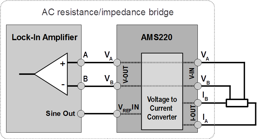
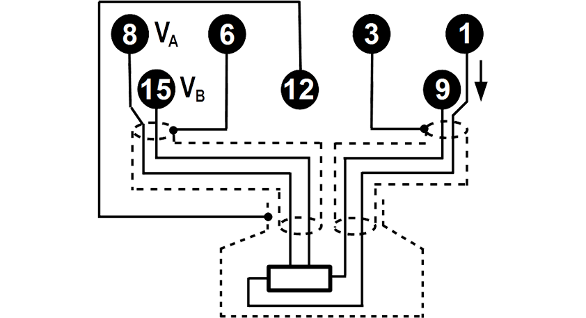
The functionality of an AC resistance (impedance) bridge can be obtained simply by interconnecting reference voltage output (Sine Out) and voltage sensing inputs of a lock-in amplifier with the corresponding inputs and outputs of the AMS220, while the tested resistance is connected to the AMS220. The excitation current provided by the AMS220 is then proportional to the reference voltage provided by the lock-in amplifier and switch-programmable voltage-to-current conversion factor of the AMS220. Connection of the AMS220 in the configuration replacing the AC resistance bridge and the principal block diagram of the signal wires and signal wire shields connected to the AMS220 are schematically shown in Fig. 1 and Fig. 2, respectively.
 Fig. 1 Block diagram of connection of the AMS220 with a lock-in amplifier which replaces an AC-resistance/impedance bridge.
 Fig. 2 The principal block diagram of the signal wires and signal wires shields. Indicated numbers represent pin numbers of the D-SUB 15 connector of the AMS220.
