How to ensure reliable results
of very-low resistance measurements
The four-wire (Kelvin) method is used to measure low resistances because it helps to eliminate errors due to lead and contact resistances. However, only its use does not guarantee correct results of very-low resistance measurements.
Measurements of low-level signals are frequently affected by common mode errors
In a typical four-wire resistance measurement as illustrated in Fig. 1, the test current (IT) is forced through the resistance (RT) being measured, and the voltage across the test resistance (VD) is sensed. The measured resistance is
RT = VD / IT.
However, in a real measurement the resistance is determined as
RT = VM / IT,
where VM is the value provided by the voltmeter sensing the voltage VD. If the input impedance of the voltmeter is sufficiently high, the effect of the sense current (IS) can be neglected. But still, especially at very-low resistance measurements, VM often differs from VD due to common-mode error, even if high-precision instruments capable to measure very small voltage differences (e.g. lock-in amplifiers)
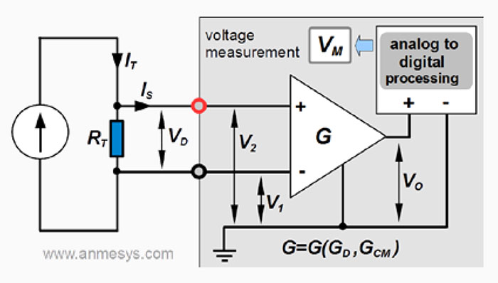 Fig. 1 Depiction of a typical four-wire resistance measurement with a block diagram of the signal processing by the voltmeter.
The value VM is based on processing of an output voltage signal (VO) of a differential amplifier (operating with a differential gain GD) at the input of the voltmeter. The output voltage of an ideal differential amplifier would be VOideal = GD(V2 – V1). However, if the voltage difference that appears across two inputs of the differential amplifier, V2 – V1 = VD, is much less than the common mode voltage VCM = (V2 + V1) / 2 (i.e. VD << VCM), then VO can significantly differ from VOIdeal. In such case, contribution coming from the common mode voltage will affect output voltage VO; the output voltage will be expressed by the equation
VO = GD (V2 – V1) + GCM (V2 + V1)/2 = GDVD + GCM VCM
where GCM is the common mode gain. The ratio GD /|GCM|, so-called common mode rejection ratio (CMRR) characterizes the extent to which the common mode voltage is rejected by the differential amplifier. The CMRR can be expressed also in decibels, being then referred to as common mode rejection (CMR); CMR = 20 log10 CMRR.
Note:
The CMR of an instrument/device is its key specification indicating how much of the common mode signal will appear in the measurement. In fact, limiting capability of instruments to reject common mode signals represents serious limitations for very-low resistance measurements (including those performed by means of Kelvin method), such as resistances in the current path can cause common mode voltage, which can be even several orders of magnitude greater than the sensed voltage (VD). Nowadays technology limit is approximately 140 dB (CMRR = 107, i.e. amplification of the differential voltage across the amplifier inputs is 10 million times greater than the amplification of the common mode signal). Typically, the CMR varies between 80 dB (CMRR = 104) and 120 dB (CMRR = 106).Common mode errors in resistance measurements can be eliminated by use of current source with active common mode rejection
Let us imagine measuring the resistance of a 100 µΩ test resistor as illustrated in Fig. 2 and Fig. 3. If current of 10 mA (AC or DC) is forced through this resistor, the voltage across the resistor is VD = 1 µV (100 µΩ x 10 mA = 1 µV).
At use of a “classical”current source with one of the outputs connected to the signal ground (single-ended current source) as illustrated in Fig. 2, if the resistance of the current path connected to the grounded output is RIB ≈ 20 Ω, then the common mode voltage VCM ≈ 20 Ω × 10 mA = 200 mV is created. Note that this value is much greater than VD. At using an industry standard lock-in amplifier with CMR ≈ 100 dB (i.e. CMRR ≈ 105) to sense the voltage, the corresponding common mode error will be ≈ 200 mV / 105 = 2 µV, thus the value provided by the lock-in amplifier being a sum of VD (1 µV) and the common mode error (2 µV) will be 3 µV instead of 1 µV. Correspondingly, the resistance gained from the experiment is 300 µΩ instead of 100 µΩ.
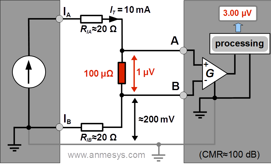 Fig. 2 Four-wire resistance measurement setup with a current source with one of the current outputs connected to the signal ground. The indicated measured value (affected by common mode error) is illustrative with regard to the discussed example.
To ensure correct result at the output of the voltage sensing instrument, the common mode voltage signals need to be eliminated. The new patented technology of active common mode rejection solves this problem.
As illustrated in Fig. 3, the patented circuit of active common mode rejection (ACTIVE CMR) implemented in the AMS220 voltage controlled current source monitors the voltage sensed by the inputs (A, B) of the voltage sensing device and using a feedback loop regulates the voltage at the current output in order to achieve that common mode voltage of the monitored signals is zero (VCM → 0 V). Thanks to the patented technology the component of VCM originating in the lead and contact resistances in the current path can be suppressed to less than few microvolts. It can be estimated that with the use of measuring device with CMR ≈ 100 dB or greater the common mode error can be eliminated to the level of tens of picovolts or less! Thus, the measured value will be as expected, 1 µV.
The AMS220 voltage controlled current source with active common mode rejection can be used with an lock-in amplifier instead of AC resistance/impedance bridge.
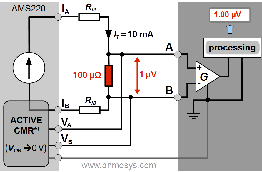 Fig. 3 Four-wire resistance measurement setup utilizing the AMS220 voltage controlled current source with active common mode rejection (*) U.S. Patent #9,285,809)